Making a Practical Compass Part 2
by Jim Hansen
This discussion flows from Part 1. It begins with a critque of the first compass design and, in using an engineering investigational approach, questions the reasons for everything in the original design, draws conclusions for improvement, then develops a new compass design.
Weve made our first attempt at a practical compass design in Part 1, where we floated our compass in water. We found that the compass worked, but had a magical attraction toward a side of the container, where it bound and no longer points north. This problem was identified as being due to the curved nature of the surface of water in a container. The surface tension creates a curved surface and anything floating on it tends to slide off the buldge in the middle, and ends up stuck against the wall of the container.
In engineering terms, the first version of the compass is a proof of concept model, meaning that we showed that our compass design can work, but not necessarily in a practical or reliable fashion. It is time now to list all the problems, and account for the design decisions that we made. From this discussion, well form a new plan, make another model and see how that works.
Our first design was to use water as a nearly frictionless bearing. It was a good idea, and the compass rapidly swung around to point north. But then the entire compass moved from the center of the container until it was stuck to the side of it. This problem had been noted in all of the "simple" compasses built using a needle, cork and a pan of water. We thought the problem might be caused by surface tension and put detergent in the water to reduce it, but the problem persisted.
A possible solution might be to build a cage around the compass, but the problem persisted - once the compass reached the cage, it was stuck there. Another idea was to install a centering post that would keep the compass in the middle of the container, and although there were signs it worked better, the problem was clearly not solved. No matter what, the compass continued to drift around until it hits something, then sticks.
So why did we use water in this design in the first place? It seemed to satisfy a number of issues, namely cheapness (as in free) and it minimized friction, and friction is what a good compass design is all about. Friction makes the compass stick, or not quite reach the true magnetic north heading. This is not a problem when a water bearing us used because water is near infinitely pliable. Water also slows down the motion of the compass so that it doesnt wildly swing. (This is called dampening the swing.) What we didnt anticipate was that things floating in a container of water float toward the side of the container. This is a fatal flaw that has to be resolved.
The centering post was the only idea we came up with that improved compass operation. Perhaps we should try removing the water entirely and support the compass on the centering post. This should eliminate the problem, but now there will be friction that the magnets must overcome. If the centering post is tapered so there is very little contact area where the compass rests, we reason that it should be able to swing freely.
The main objection to the centering post idea is that if it is going to be used, it must also provide a low friction bearing. This means a major change in our compass design is needed.
The centering post actually simplifies our compass design. We found a need for the centering post, whether we continued development of the water-float based design or not. So we will develop some sort of really low friction, cheap bearing and see how it goes. If that doesn't work, perhaps a combination of centering post, bearing and water floatation can be tries. And looking just a little ahead, we will have to have a solution for what happens when the water freezes. But for now, it looks like water has to go.
That leaves us with the task of designing a dry compass, one with a lower bearing whose sole purpose is to keep the compass over the centering post, and a top or pivot bearing which carries the weight of the compass rose and magnet. Since all the weight of the compass will be carried by the top bearing, it will be the main source of friction.
For now, we'll limit our solutions to those that can use inexpensive supplies from a craftstores such as Michaels and the local hardware store. Students should be made aware that this version of the compass will take more time, patience, care and craftsmanship to assemble this one than before. But the results will be worth the effort.
The completed compass looks more compass-like than before. Notice that this is not a final design. Rather, we are using it to prove that we have solved the "drift" problem and can make a compass that actively points north under most conditions. For now well drop the portability requirement until this version has been built and tested.
Supplies
Although this is a fairly long list, the cost is still under a dollar. For each compass you will need the following:
1 - 6mm Pearl Bead (top bearing)
1 - 3mm glass bead (bottom bearing)
1 - Bell cap to top off the bearing stack
1 - Soda straw with about 6mm inside diameter
1 - Sheet of card stock to print compass rose on
1 - Milliners needle (a fine needle about 1.5" long) to serve as the centering post and pivot
1 - Piece of foam board or equivalent for base of compass
1 - Some 5 Minute Epoxy or equivalent
Tools
Paper clips, tweezers, scissors, small file (a nail file
will do), optional electric iron and doll needle (a really
big needle 3 or 4 inches long), good lighting, access to a drill press and numbered
set of drills.

Print the compass rose (provided in Part 1) onto card stock. If you are providing these for students, you can print four per sheet. Also, consider making a negative version which will give black lettering on a light background. Some card stock curls after printing. If this is the case, glue a second copy of the rose back-to-back with the first. Ironing or pressing in my experience does not cure this problem.
After the rose has been cut out (with emphasis on careful cutting - you dont want it out of balance) carefully mark the precise center of the rose by using a straight edge across the rose from the 0 - 180 and 90 - 270 markings.

Using a drill press and a number 42 or 43 drill bit, drill a hole in the center of the compass rose card. Prevent ragged edges by drilling about half way from one side, flipping the card and completing the hole from the other side. If you do not have access to numbered drills, use one that will give a tight fit for the lower bearing.
Youll find that handling the glass bead and pearl bearings is difficult unless you first thread them onto a paper clip or wire. Then they are much more manageable. A really large needle is also useful for moving them around.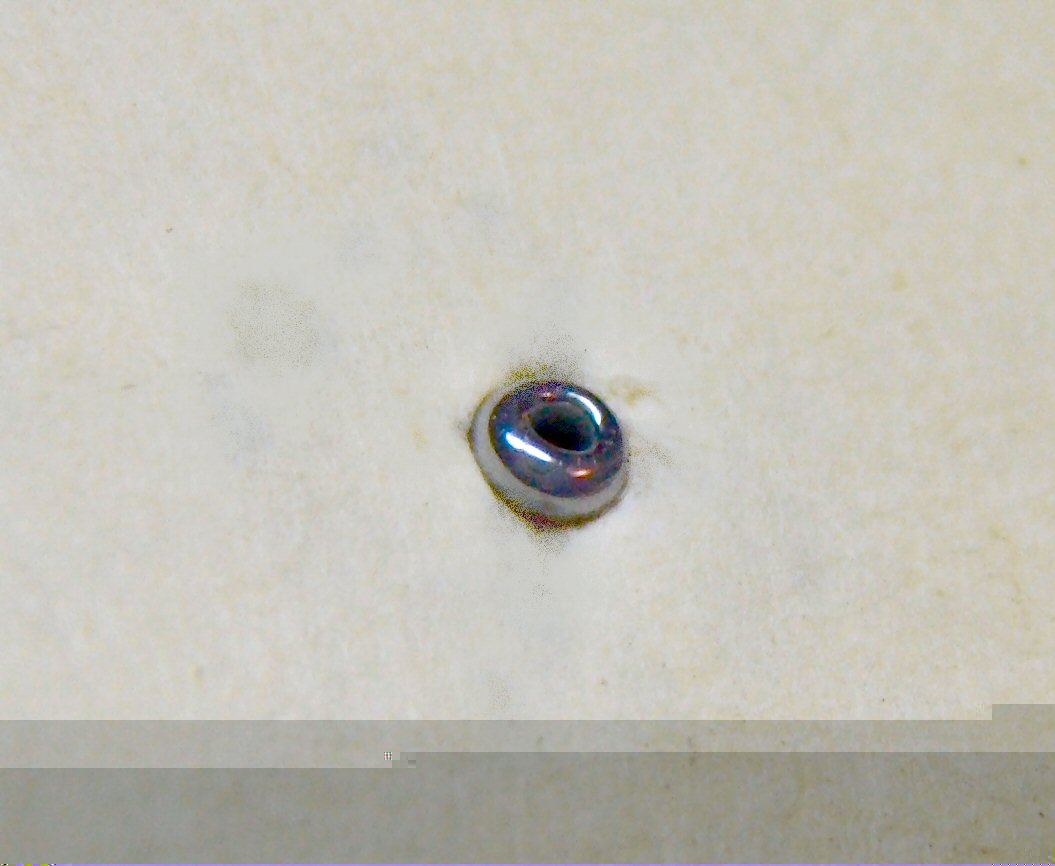
Carefully press the 3mm glass bead into the hole. Set the bearing so it protrudes equally from the top and bottom. Set the compass rose aside for gluing a bit later.
A pearl bead is used for the top bearing. This type of bead is made of plastic and is therefore a soft material. Ideally we would use a glass surface for this bearing which would give much less friction, but finding a suitable source for this will be left for another day. The following describes the work to be done on the pearl bearings.

Cut a length of plastic straw about an inch long, making sure it is considerably shorter than your needle used for the centering post plus the thickness of the base. The straw forms the shaft holding the pearl pivot bearing. Test the fit of the pearl and if it is loose, roll the pearl in a cylinder of cellophane (Scotch) or masking tape and test again. The holes through the pearl should be sideways, with the tape completely covering them. Cut the tape off so it doesnt go past the bottom of the pearl. You can use the tape hanging off the top of the pearl to hold it with for the time being.

File a flat spot on the pearl, through one of the exposed ends. Then take the pearl to your drill press and using a numbered drill between #60 and #50, drill a hole just a little ways into the pearl. Don't drill so far that you hit the hole already in the pearl. The only requirement is that this drill be larger in diameter than the needle being used as the centering post.
Test assemble your compass on a temporary test stand. Put your Milliners needle in the drill press. Without the motor running, press it through your foam core bottom piece. The idea here is to set the needle vertically into the base with the scrap being used to shorten it. Don't even think that you can set the needle vertically by hand. You compass performance depends on the centering post being as close to vertical as you can make it.
Punch a hole that will easily clear the compass rose bearing into several pieces of scrap card stock, then place them over the needle. These will let you put the compass rose on the needle without knocking the lower bearing out of it. Carefully lower the compass rose over the needle centering post.
This step will take some patience! Gently press the pearl into the cut end of your straw with the drilled hole facing straight down the straw. Set the straw over the bearing on the compass rose, centering it over the needle. If the straw doesnt reach the compass rose, remove it and push the needle down a little, then retry the fit. DONT PUSH THE NEEDLE DOWN WITH THE PEARL! This will deform the bearing and add friction. If the needle protrudes too much, remove the straw and push it back by hand. Lastly, put the bell cap on the top of the pearl bearing.
Once you are satisfied that everything fits, it's time to mix up a small batch of 5 Minute Epoxy or equivalent epoxy cement. Caution: this stuff sticks to everything. If you get any in the lower bearing or in the pearl hole, youll just have to start over; it cant be saved. If available, use acetone to remove the stickiness from your hands. The technique being used here is called "self-fixturing." The idea is that the needle (our centering post), when passed through the lower bearing will properly align the top pivot bearing, assuring that the assembly is true and that the compass will hang vertically on the pivot. When the centering pin is eventually raised to its finish height, the compass rose clears the base and swings freely.
Remove the straw and using the end of a bent paper clip, carefully put a ring of epoxy around the lower bearing on the compass rose. Apply by just touching the compass rose next to the bearing and let the epoxy run down the wire and wick to the bearing without your help. Once this has hardened, an hour or more later, flip the compass card and do the same on the bottom.

Epoxy the pearl in the straw by putting a ring around the top end of the inside lip of the straw. Then completely cover the pearl and make sure the epoxy reaches the inside edge of the straw. Next, put a ring of epoxy around the OUTSIDE edge of the bottom end of the straw. You can be more generous here. Quickly drop the straw over the needle and thread it into the hole of the pearl - without letting any epoxy touch the centering post.
The bottom of the straw should now be resting on the compass rose and you can add a little epoxy around the bottom if you like. Lastly, carefully set the bell cap on the top of the straw and using just tiny dabs of epoxy, glue it in place. This last step can wait until later if you like, after the other glue hardens. Give the compass one last inspection, making sure that the straw is perfectly perpendicular with the compass rose.

After this dont move anything, dont wiggle anything, and dont even look at the compass for at least 30 minutes. But after that, remove the compass from the needle, and remove the extra card stock and foam board from it. Press the needle until it is flush with the bottom of the base, then mix just a little more epoxy and put a dab around the needle protruding from the top of the base. Let your compass sit overnight completely unbothered while the epoxy hardens.
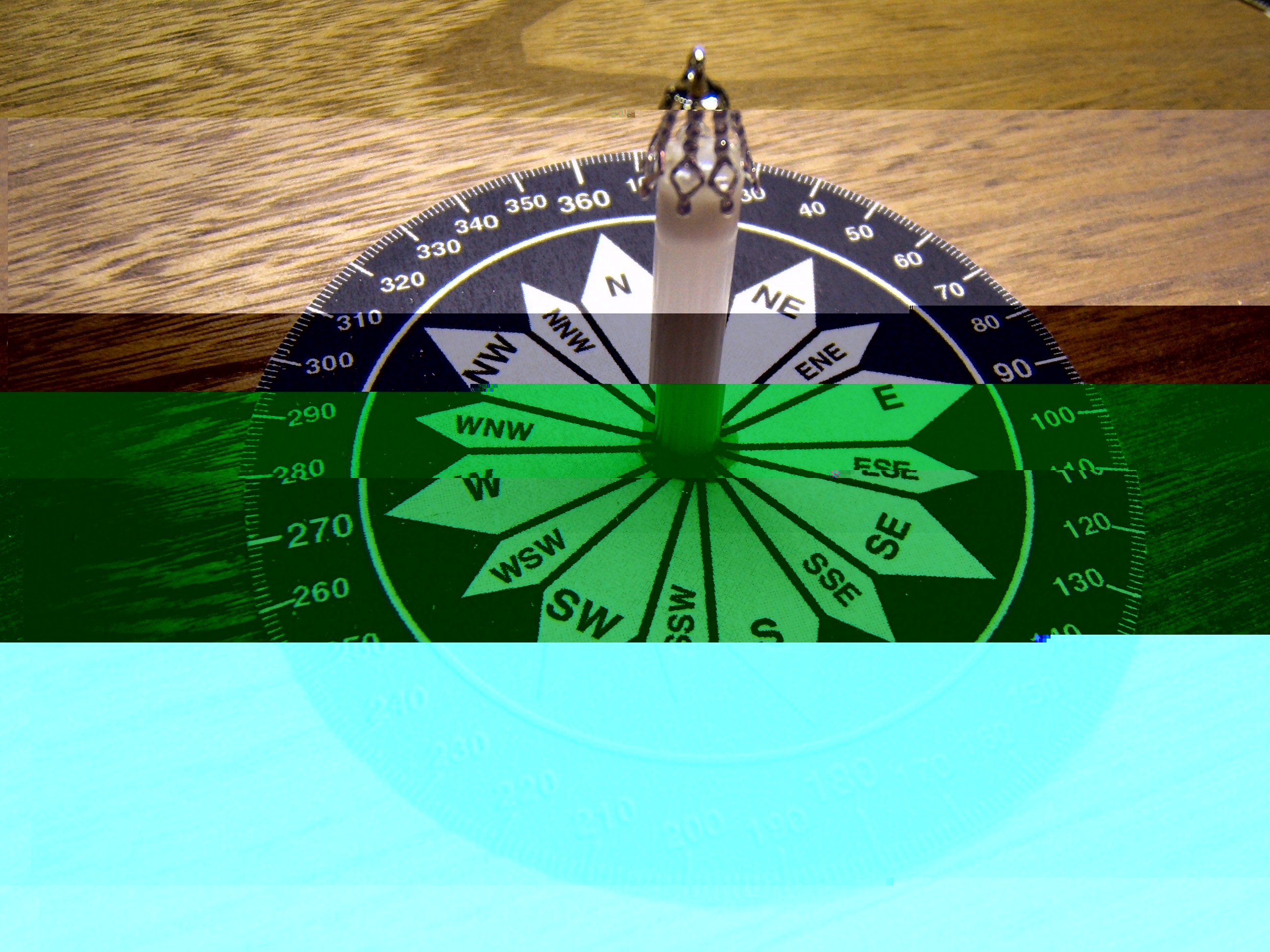
Assemble your compass, remembering to never apply any force downward on the pearl bearing. It may take some effort to make sure that the needle point is in the hole drilled in the pearl. But once there youll have a remarkably free-turning wheel. Check it out. You can start it spinning by just breathing on one side of it! Remove the compass rose assembly and place a small neodymium magnet with its north pole facing outward at the 360° mark. You can test this by holding the magnet in place with a piece of tape. Place another identical magnet facing the same direction at the 180° mark. Once correctly set in place, glue the magnets into position.

Why two magnets? We have to keep the magnets as far from the (magnetic) needle center post as possible and for best performance, we must keep the compass rose mechanically balanced over the pearl. Also, the force that the magnets excert is multiplied against the bearing friction because they are working from the end of what is effectively a "lever."
Reassemble the compass, remove all magnet material from around the compass and watch the action. This compass seeks north like no other compass youve likely seen. But notice the overshoot! It swings past north, then swings back. If you move the compass to point 180̊ in the wrong direction and release it, you should be able to easily count more than 30 "boings." This is called oscillation and although the compass will eventually settle down, it makes actual use of it difficult. The compass needs to be dampened so it doesn't keep swinging back and forth. This is one of the functions that water served in our first design.
You might wonder how we can slow down or eliminate this oscillation, and this problem is one we'll work on in Part 3 of this series. The solution here is a compromise that design engineers always face, and it hurts: we have to add friction to the system that we so carefully designed to be friction free. (If the compass were completely friction free, it would never stop spining back and forth.) But we want a special kind of friction, not just drag. We want a friction that only resists motion. We want friction that increases with the speed of the compass swing, but drops to nothing when the compass stops.
There is a way to make this sort of magic happen, and the phenomenon is called electro-dynamic dampening. And how can we add it to our compass? You need only cut out a piece of sheet aluminum and mount it under the compass rose where the pointing magnetic field can reach it. When the magnets on the rose move, they will induce a voltage into the aluminum, which in turn creates an opposite magnetic field that slows down the swing.
The result is that the faster the compass rose turns, the greater the induced voltage, and the greater the friction it generates. And the slower the compass turns, the less magnetism is generated, and the lower the friction. It almost entirely stops the oscillation that you see, doesnt doesn't affect accuracy, leaving a very sensitive, working compass. But this is a fairly major effort, and only the brave need consider it.
We have reached the end of this part of this project. Those who continue on to Part 3 will surely be tested: we'll have to make improvements to our center post bearing, and get our dampening to work. Keep in mind, we're still building a prototype, but version 3 should start to come together as a truly workable compass!
Notes: Magnetic compasses are as accurate as your magnet alignment with the compass card allows. But to make it into a truly precise and reliable instrument, it still needs a lot of focused, handcrafted work. The compass of Part 2 is of unusual freedom and sensitivity, but is not very resilient. The needle used for the centering post will rapidly wear the bead used as the pivot bearing. The reasons are that the needle is a sharp point (it needs to be rounded) and the pearl is just plastic, a soft material that will rapidly wear.
This compass is also quite fragile. It will undoubtedly be physically damaged even if carefully handled. But it contains every design element of a precision tool. Not only that, the cost is less than a dollar and all parts can be commonly purchased through craft and hobby stores. We will spend a couple of dollars on our next compass design, but it should end up being close to practical.
Here are the most important issues that must be addressed in Part 3:
1. The compass rose assembly must be made flat, precisely balanced and as light as possible.
2. The pole (compass direction) magnets are very powerful, and thus sensitive to ferrous (iron) materials that might be nearby. While building the prototype compass shown here, a pair of accidentally magnetized scissors more than a foot away caused an error of almost 30̊ . With high performance bearings, we can reduce the strength of the magnets and still obtain a very positive compass response. Whether or not we reduce the strength of the magnets, external influence is an important problem that needs resolution.
3. Two magnets were used to mechanically balance the compass and ensure that we had balanced fields on either side of the magnetic centering post. Positioning them far away from the centering post gains mechanical advantage over the friction of the bearing, but complicates precise magnetic alignment, not to mention precision balance of the system. The magnet setup is an area that we blissfully ignored, but a true instrument builder would spend many hours working out the best solution.
4. The compass rose pivot bearing in a precision compass instrument would never be made of plastic. A ruby and non-magnetic polished stainless steel shaft would be ideal for this construction. We need a bearing solution that will give a lifetime of flawless service - and be cheap!
5. Compass dampening must be applied to any practical compass, especially a precision one used for navigation. There are many ways of accomplishing this, including submersion in oil.
6. The entire compass assembly should be gimbal mounted so that its shaft is always vertical, no matter what the position of the ship or aircraft. A simple gimbal could be made to hold our compass, but that is a detail will be left for another day.
7. A means of preventing the compass assembly from lifting off the pivot must be made. In most compasses, this is accomplished by placing the viewing window just above the pivot so that it is impossible for the compass assembly to lift far enough to disengage from the centering post.
8. We did not provide for a means to lock the compass, or lift it from the pivot pin to protect the bearing. This refinement in a naval compass is not useful since the binnacle compass is typically in use 24/7 whenever the ship is at sea. But it is a useful consideration.
9. We provided no lighting for night time use of the compass. For now this is a task that we can confidently presume would be easily solved by anyone wanting to read our compass at night.
Any student who has the interest, patience and craftmanship to get through Part 3 of this series, which will be taking on the above problems, is a young person that I'd like to correspond with.
Lastly, thank you for reading so far. I hope and trust you've enjoyed it and I welcome your comments. Write to me, Jim, at jimsmath@jimsmathandscience.com.